Signal Conditioning

| About Us | Careers | News | FAQs | Product Overviews | Exhibitions | Contact Us
Mon - Thu 8am to 5pm | Fri 8am to 4pm

Signal Conditioning

In electronics, signal conditioning means manipulating an analogue signal in such a way that it meets the requirements of the next stage for further processing. Most common use is in analogue-to-digital converters. A full range of signal conditioning option which includes amplifiers for all the sensor types, panel meters with integral sensor power supplies, and wireless products. All can be configured to provide a total system from sensor to the final signal required. Signal conditioning can be used to directly power the sensors and receive an input signal such as accelerometers, strain gages, temperature sensors with cold-junction compensation, however be sure to note the sampling rate required. Generally the signal conditioner provides a small voltage up to approximately 10 volts. Signal conditioning can be used as part of a data acquisition system to provide monitoring and control.

Download signal conditioners overview 
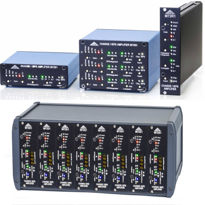
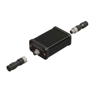
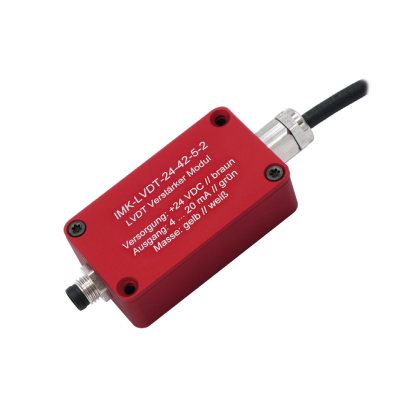
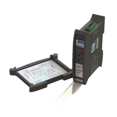
Signal Conditioners Overview

Please wait, loading results...

Amplifier Accessories

View Products

Amplifier Load Cell & Strain Gauge

View Products

Amplifier LVDT

View Products

Amplifier Pressure

View Products

Displays Handheld

View Products

Displays Panel

View Products

Multichannel Modular Signal Conditioner

View Products

Wireless Telemetry

View Products

Frequently Asked Questions About Signal Conditioners

Need Help with Signal Conditioning?

Signal conditioning is crucial for accurate data acquisition. Learn about amplification, filtering, and signal processing techniques.

Signal conditioning is the process of manipulating a signal in a way that prepares it for the next stage of processing. It is the manipulation of an analogue signal in such a way that it meets the requirements of the next stage for further processing. Most common use is in analogue to digital converters.

Most of the transducers (the sensors that convert physical measurement into electrical signal) produce the signal in the range of millivolts or milliamps. Such signals need to be amplified, filtered and isolated for precision measurement and control. The functions of signal conditioning include amplification, filter, electrical isolation, multiplexing, transmitting etc.

Signal conditioning is essential for several reasons:

  • Signal Compatibility: Many sensors produce signals that are not directly compatible with measurement systems. Signal conditioning ensures the signal is in the right format and range.
  • Noise Reduction: Industrial environments often have electrical noise that can corrupt sensor signals. Signal conditioning includes filtering to remove this noise.
  • Protection: Signal conditioners protect expensive measurement equipment from voltage transients and ground loops.
  • Accuracy: By amplifying weak signals and providing proper scaling, signal conditioning improves measurement accuracy.

The main functions of signal conditioning include:

  • Amplification: Increases the level of the signal to match the range of the analog-to-digital converter, thus increasing the resolution and sensitivity of the measurement.
  • Filtering: Removes unwanted frequency components from the signal, such as noise or interference from 50/60 Hz power lines.
  • Isolation: Breaks ground loops and rejects common-mode voltages, protecting both the measurement system and the operator.
  • Linearization: Converts non-linear sensor signals to linear representations of the measured parameter.
  • Excitation: Provides power or excitation signals required by active sensors like strain gauges or RTDs.
  • Cold Junction Compensation: Compensates for the ambient temperature at thermocouple connections.

Most sensors require some form of signal conditioning. Common examples include:

  • Thermocouples: Require cold junction compensation, linearization, and amplification due to their low millivolt output.
  • RTDs and Thermistors: Need excitation current, linearization, and lead-wire compensation.
  • Strain Gauges: Require excitation voltage, bridge completion, and amplification of their small millivolt signals.
  • Load Cells: Need excitation, amplification, and sometimes filtering for weighing applications.
  • Accelerometers: May require charge amplifiers (for piezoelectric types) or voltage excitation (for MEMS types).
  • Pressure Transducers: Often need excitation and amplification, with some requiring ratiometric measurements.
  • LVDTs: Require AC excitation and demodulation to extract position information.

When selecting a signal conditioner, consider the following factors:

  • Sensor Type: Ensure compatibility with your specific sensor (thermocouple type, strain gauge configuration, etc.)
  • Input Range: Verify the conditioner can handle your sensor's output range and signal levels.
  • Output Requirements: Match the output (0-10V, 4-20mA, digital) to your data acquisition system.
  • Accuracy: Choose accuracy specifications that meet your measurement requirements.
  • Bandwidth: Ensure sufficient frequency response for dynamic measurements.
  • Environmental Conditions: Consider temperature range, humidity, and vibration specifications.
  • Isolation: Determine if galvanic isolation is needed for safety or noise rejection.
  • Power Supply: Check available power sources and consumption requirements.

Active Signal Conditioning:

  • Requires external power supply
  • Can provide amplification and signal gain
  • Includes active filters with sharp frequency cutoffs
  • Offers features like excitation, linearization, and isolation
  • Examples: operational amplifier circuits, instrumentation amplifiers

Passive Signal Conditioning:

  • Does not require external power
  • Limited to attenuation, not amplification
  • Uses passive components (resistors, capacitors, inductors)
  • Simpler and more reliable but less flexible
  • Examples: voltage dividers, RC filters, bridge completion resistors

Common challenges in signal conditioning include:

  • Ground Loops: Multiple ground connections causing current flow and noise. Solution: Use isolated signal conditioners.
  • Electromagnetic Interference (EMI): External fields inducing noise. Solution: Use shielded cables and differential measurements.
  • Thermal Drift: Temperature changes affecting accuracy. Solution: Use temperature-compensated designs and stable references.
  • Common-Mode Voltage: Voltage present on both signal lines. Solution: Use instrumentation amplifiers with high CMRR.
  • Aliasing: High-frequency noise folding into measurement band. Solution: Apply anti-aliasing filters before digitization.
  • Impedance Matching: Source and load impedance mismatch. Solution: Use buffer amplifiers or impedance matching circuits.

To test and troubleshoot signal conditioning systems:

  • Calibration Check: Use known input signals or calibrators to verify the system's accuracy across its range.
  • Signal Tracing: Use an oscilloscope or multimeter to trace signals through each conditioning stage.
  • Noise Analysis: Check for 50/60 Hz interference, high-frequency noise, or intermittent spikes.
  • Power Supply Verification: Ensure clean, stable power within specifications.
  • Connection Integrity: Check for loose connections, corroded terminals, or damaged cables.
  • Grounding Inspection: Verify single-point grounding and absence of ground loops.
  • Temperature Testing: Test performance across operating temperature range.
  • Documentation Review: Verify settings match sensor specifications and system requirements.